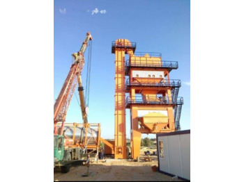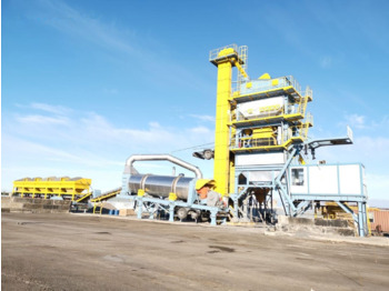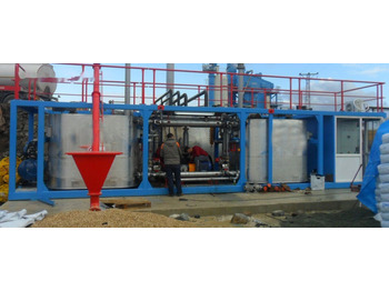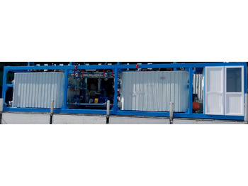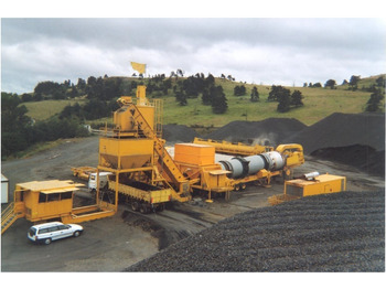
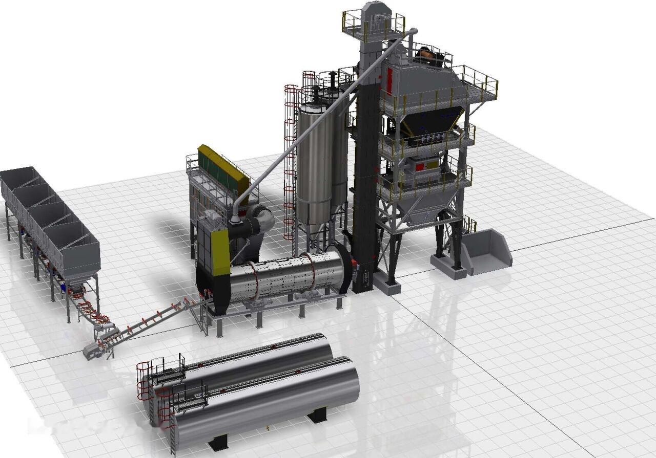
New Asphalt plant Polygonmach PBA-160 batch type stationary asphalt plant
Published: 16d


Published: 16d
Do you need shipping?
STANDARD CONDITIONS The plant is designed for a production of, 160 t/h of road mix with a finished product at initial moisture 4% and of 160 C, under the following standard conditions:
•Aggregates temperature at dryer inlet 10 C
•Altitude sea level
•Average feed aggregates density 1.650 kg/m3
•Heavy-oil No: 6 calorific value ≥ 9.200 kCal/kg
•Heavy-oil No: 4 calorific value ≥ 9.700 kCal/kg
•Diesel-oil calorific value ≥ 10.200 kCal/kg
•Natural gas calorific value ≥ 7.600 kCal/kg
•Hot aggregates temperature increase 160 K
•Mixture residual moisture content 0,3 %
•Max. aggregates size 40 mm
•Material passing screen 3 mm 35 %
•Material not porous and hygroscopic with normal shape
•Production tolerance rate according to ambient and parameterconditions ± 4 %
COLD AGGREGATE BUNKERS
•There shall be 4 cold aggregate bunkers made of 5 mm St 37 sheet, they shall be approximately20 m3 and each one shall be produced separately.•There shall be 800 mm high upper additions made of 6 mm sheet on the bunkers to preventmaterial overflow.•Material cast of the bunkers shall be made with mot.red group.•Material cast flow rate of each bunker shall be frequency controlled (speed controlled) dozingone by one if desired or adjustable from computer screen.•The flow rate of the material flowing from bunkers shall be adjustable from the manual gate to beplaced on each bunker.•In case of running out of the aggregate flowing from the bunkers, there shall be a warning systemand a warning sign shall be displayed on the computer screen to warn the operator.•Vibrator engine controlled from computer screen shall be placed to relieve material flow andprevent blockage in the bunkers with thin materials.•A conveyor belt system shall be installed under each bunker to ensure material flow.•Each bunker shall be equipped with modular gratings consisting of 10x50 metal sheets 10mmrounds.•Silo loading width shall be 3000x2400 mm.•There shall be rope emergency stop system for emergencies.•Possible failures on belts shall be displayed on the computer screen.
2.SUB-BUNKER COLD AGGREGATE COLLECTOR BELT
•Horizontal belt shall convey the material taken from each bunker separately in a controlledmanner to the dryer sloped belt and be able to convey material to 160 t/h capacity plant.•Rubber belt shall be 10 mm thick; 800 mm wide 4 layered court fabric and have 4 EP 125qualities.•Belt Start/Stop operation shall be performed from computer screen. When the materials in thebunker are desired to be discharged at the end of the season, the belt may be run reversewithout running the other units.•Horizontal belt chassis shall be made of steel construction material by which the belt can operatesmooth and produced with belt tensioning system.
•The belt shall be with separator system from each end.
•The driving drum shall be rubber coated and it shall be 1 degree angle lathed.
•There shall be rope emergency stop system for emergencies
•Possible failures on belts shall be displayed on the computer screen.
•The belt shall be 7,5 kw d/min red./motor driven, driving drum shall be rubber coated, the beltshall be able to be driven triple roller chassis. The bearings in the roller shall be enclosed type andmaintenance-free.
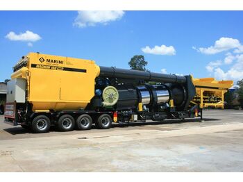
3.DRYER GROUP
•Dryer body shall be manufactured from 10 mm thick 1,800 mm diameter, 7,500 long SAE 950 Cspecial alloy heat resistant manganese steel sheet metal.
•Inside of the dryer shall be made of winged buckets made of heat and corrosion resistant specialalloy steel sheet metal to ensure that materials dry and move homogenously thoroughly.
•There shall be two peripheral rings to ensure that the dryer body rotates circularly smoothly onthe chassis. (to be imported)
•Dryer body shall be rotated by 4 red./motors on 4 idler rollers on chassis.
•The ring and the running surfaces of the idler rollers shall be hardened by induction, thusavoiding corrosion of the running surfaces.
•Dryer body shall be wrapped with a 50 mm rock wool and coated with stainless sheet metal toavoid heat loss during operation.
•There shall be a frontal gate made of heat and corrosion resistant material in front of the dryerbody and chassis for connection of the burner and to ensure dried material is cast on theaggregate elevator.
•There shall be a gate with gas outlet channel behind the dryer body and chassis for removal ofthe dust in the body through filter during operation and to ensure material from feed sloped beltis cast in the drier.
•The design of the dryer shall be made to ensure the incoming material moves forward smoothly.
•Dryer body shall rotate between the gates placed in the front and behind. There shall be a mazesystem to avoid the material to flow out in the rotation places.
•An electronic heat indicator shall be put at the point where the aggregate heated in the dryer iscast on the elevator, thus tracking the aggregate heat from the control cabinet.
•Dryer chassis shall be produced from durable material suitable for the body, sub conveyor legsshall be connected to the chassis with joints and leg intervals shall be enforced with crossconnections.
•Dryer driving system shall be equipped with SOFT-STARTER, which shall prevent Ring and ringrollers from exposing to impacts and their economic life shall be extended.
•The current value drawn by the drier motor shall be displayed on the computer screen. Thanks tothis system, the automation system and operator shall prevent the drier from being overloadedand protect the drier system from possible failures or damages.
4.DRYER BURNER
•Dryer burner shall be full automatic industrial type suitable for 160 t/h plant at 4% humidity rate.•Diesel oil can be used as fuel in the burner.•Burner shall be fired from the cabinet and fuel system shall be supported with a pump andsuction of the pump shall be protected with a filter.•In case of using fuel oil in the burner, the preheater shall be heat exchanger group.•Outer surface of the piping system coming to the burner shall be isolated.•Flame height of the burner shall be increased or decreased from computer screen.•Flame height of the burner shall be adjusted from computer screen (in %).•Start/Stop operation of the burner shall be performed from computer screen and the phasesafter the burner is ignited and failure details shall be displayed on computer screen. In case of afailure connected to the burner, the operator shall see the where the failure has occurred andimmediately respond to the failure.•Aggregate temperature, filter inlet temperature and fuel oil temperature shall be displayed oncomputer screen. When such temperatures exceed the limit values, warning signs shall bedisplayed on the computer screen to warn the operator. After some time when suchtemperatures exceed the limit values, the burner shall be automatically stop by the automationsystem, thus preventing the filter group or other units from being damaged.•There shall be a censor (vacuum meter) system to measure the counter pressure in the drier.
5.DRY DUST SUPPRESSION FILTER and FILLER SILO GROUP
•Filter plant shall filter and remove the dust particles discharged from 160 t/h capacity dryerand screen top to the air via fan.25.000 m3/h•Filter shall also filter the gas created by the burner.•Fan value and motor power to be used in filter suction shall have required capacity for 160 t/h plant.•There shall be servo-motor driven valve in front of the fan to adjust the flow rate of the fan.•The command of the valve in front of the chimney fan shall be controlled automatically by theautomation system by means of the vacuum meter measuring the drier counter pressure.Additionally, it can be controlled by the operator from the computer screen if desired.•Through such system, the fan flow rate shall be adjusted automatically depending on the systemrequirements, thus increasing economic lifetime of bags and saving power.•The value of the counter pressure shall be followed up on computer screen in mmSS.•Filter shall be dust bag and cassette type or reverse flow, pneumatic controlled valve cap, andthere shall be a pre-separator.•Filter body shall be installed on a bunker and rough particles shall be avoided to harm beingcollected in a separator and bunker space and reaching to the bags.•Filter shall be connected to the dryer via a channel.•Nomex filter cloth shall be used in the filter system.•There shall be platforms, banisters and ladders where required in the filter.•Reaching the material collected under the bunker to the filler elevator shall be ensured with tubespiral.•As soon as the filter body exceeds 180 degrees, fresh air adjustment valve shall be put to cool thefilter.•On/off position of the fresh air adjustment valve of the filter shall be seen on computer screen.•In the event that the temperature of the filter cannot be reduced for any reason, the plant shallautomatically stop to avoid burning of the bags.•The surface of the filter shall be isolated 50 mm glass wool and coated with aluminium sheet.•The system shall incorporate a 25M3 (2 PCS) capacity of filler silo.
•The filler silo shall be installed between the filter and the filler elevator and designed toautomatically stock up the filler in the hot aggregate bunker and to deliver to production whenneeded.
•The filler silo shall be equipped with a level indicator and a filler discharge spiral.
•Start/Stop operation of the filter group shall be performed from computer screen. Possiblefailures can be seen on computer screen.
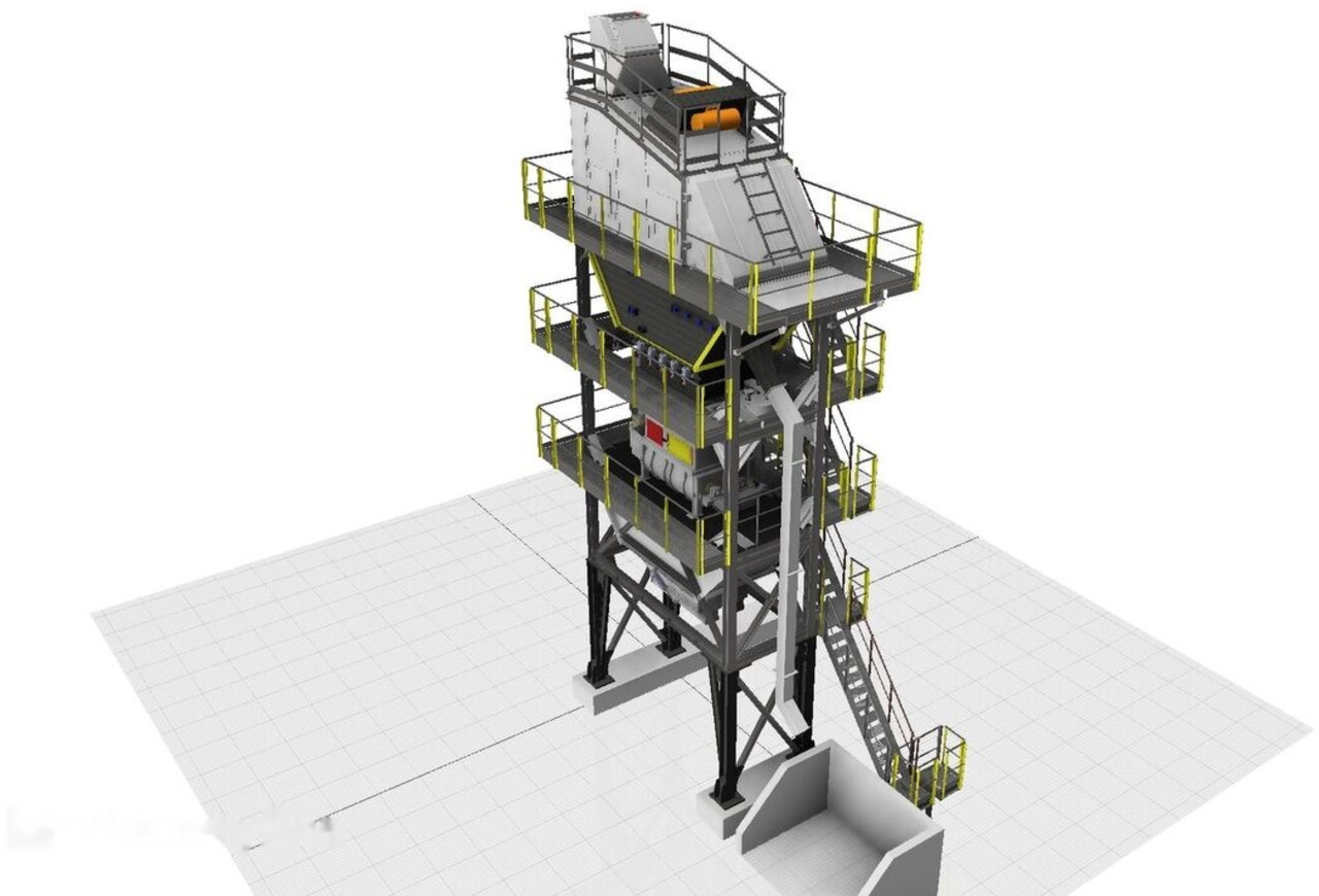
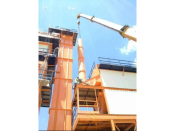
6.TOWER GROUP AGGREGATE ELEVATOR
•Aggregate elevator body shall be produced from 5 mm sheet metal, its lateral surfaces beingreinforced and in two pieces whose shipment is complete mounted.•Aggregate elevator shall be designed to convey the aggregate heated in the rotating dryer to thescreen on the tower.•Body joining parts of the aggregate elevator shall be flange connected and sealed.•There shall be maintenance gates on the aggregate elevator body for bucket replacement andmaintenance.•In the event that the aggregate elevator stops for any reason during operation, there shall be areturn lock installed in the drive group to ensure the loaded buckets become upside down andblock elevator.•There shall be a chain tensioning system on the aggregate elevator.•Aggregate elevator shall be driven by Motor/red, chain and chain gear group.•Aggregate elevator buckets shall be produced from st 52 3 mm sheet metal and bucket edgesshall be reinforced with 5 mm st 52 material.•Aggregate elevator chain shall be HRC 35 – 45 hard special produced chains. Minimum 35 mm 2chain gear whose running surface is hardened shall be used at the bottom and top on theaggregate elevator for drive of the chain and buckets.•There shall be a platform and banister group where there is the drive group of the aggregateelevator.•Aggregate elevator shall be able to feed 160 t/h plant.•The red.motor cable of the drive group of the aggregate elevator shall pass through the tubewelded on the body in a steel tube suitable for cable diameter and be connected mot.red.•Start/Stop operation of the aggregate elevator shall be performed from computer screen. Failuredetails of the aggregate elevator can be seen on computer screen.•The current value drawn by the aggregate elevator shall be displayed on the computer screen.•Thanks to this system, the automation system and operator shall prevent the elevator from beingoverloaded and protect the plant from possible failures or damages.
7.TOWER GROUP FILLER ELEVATOR
•Filler elevator body shall be produced from 4 mm sheet metal to be delivered in complete and mounted.•Filler elevator shall be designed to convey the filter bunker and the filler in the filler silo to the filler weight stock bunker.•Body joining parts of the filler elevator shall be flange connected and sealed.•There shall be maintenance gates on the filler elevator body for bucket replacement and maintenance.•In the event that the filler elevator stops for any reason during operation, there shall be a return lock installed in the drive group to ensure the loaded buckets become upside down and block elevator.•There shall be a weighted type chain tensioning system on the filler elevator.•Filler elevator shall be driven by Motor/red, chain and chain gear group.•Filler elevator buckets shall be produced from st 52 3 mm sheet metal and bucket edges shall be reinforced with 6 mm st 52 material.•Filler elevator shall be driven by Motor/red, chain and chain gear group.•10 mmX300mm thick EP125 heat resistant 4 layer cordless endless band will be used in the filler elevator•Filler elevator shall be able to feed 160 t/h plant.•The red.motor cable of the drive group of the filler elevator shall pass through the tube welded on the body in a steel tube suitable for cable diameter and be connected mot.red.•Start/Stop operation of the filler elevator shall be performed from computer screen. Failure details of the filler elevator can be seen on computer screen.
8.TOWER VIBRATING SCREEN
•Vibrating screen shall be produced 4 layered to sort the heated aggregate from aggregateelevator into 4+1 types.
•Vibrating screen shall be placed on helical springs from 4 lateral points and designed to beworking with 2 vibrational motors system.
•Tensioning system of the internal screens shall be spring tensioning system.
•To ensure the asphalt plant operates by-pass, there shall be pneumatic cylinder controlled two-way valve at the vibrating screen entrance.
•Start/Stop operation of the screen shall be performed from computer screen. Failure details ofthe screen can be seen on computer screen.
•Screen/by-pass selection shall be made on computer screen. In case of a failure of the screen, thesystem shall be taken to by-pass position and production can be continued.
•There shall be a conveyor channel to avoid blockage of the screen by possible material on thescreen or excessive aggregate; such material shall be conveyed to a stock silo through theconveyor channel.
•Vibrating screen shall be produced to have platform banisters on its top and sides.
9.TOWER GROUP SUB- SCREEN HOT AGGREGATE BUNKER
•Hot aggregate bunker shall be produced to consist of 4 chambers with 15 m3 volume in total tosend the material screened to the weighing scale.
•Pneumatic controlled gates shall be placed on the outlet passage of each chamber under the hotaggregate bunker and a separately controlled gate shall be placed on the outlet passage of the0,5 material for fine weighing.
•There shall be a 25 m3 filler stock chamber whose outlet is emptied with a star valve.
•There shall be an air shocking system to avoid blocking in the filler chamber.
•Hot aggregate bunker shall be produced from 5 mm sheet metal and its outer surface shall beproduced to be insulated with 50 mm glass wool and aluminium trapeze sheet.
•Each sub-screen hot aggregate silo shall be equipped with a maximum level indicator.
•Before the silos are filled fully, a warning sign shall be displayed on computer screen and theoperator shall respond to cold silos before the silos overflow.
10.TOWER GROUP MIXER FLOOR CHASSIS1.AGGREGATE MIXTURE WEIGHING SCALE11.There shall be an aggregate mixture weighing scale on the tower mixer chassis to weigh the material required for mixture.12.Aggregate mixture weighing scale shall be produced to weigh approximately 3 000 kg material with load-cell from 4 points and automatically smoothly and quickly discharge.13.Material amount in the aggregate mixture weighing scale shall be displayed on digital indicator and computer screen in the control cabinet.14.Weighing shall be made manually or automatically by computer depending on the choice.15.Material values required to make weighing automatically (receipt values) shall be entered from computer screen. Limitless number of receipts can be created. Receipt values and receipt name can be changed any time.16.Any desired sub-screen silo gate can be opened from computer screen by the operator even if weighing is automated.17.In case of overloading of the weighing scale, a warning sign shall be displayed on computer screen and the operator shall be warned.
•The information that “the pneumatic gate of the aggregate weighing scale is open” shall be displayed on computer screen. In the event that the gate does not open completely for some reasons during automatic production, the production shall be suspended by automation system and the information about the failure shall be displayed on computer screen.2.FILLER MIXTURE WEIGHING SCALE•There shall be a filler weighing bunker on the tower mixer chassis to weigh the filler material required for mixture.•Filler mixture bunker shall be produced to weigh approximately 300 kg material with load-cell and its discharge passage shall be able to discharge with pneumatic cylinder controlled valve.•There shall be 219 mm diameter mot./red. Driven pipe spiral to send the material weighed filler mixture weighing bunker to the mixer.•Material amount in the filler weighing bunker shall be displayed on digital indicator and computer screen in the control cabinet.•Weighing shall be made manually or automatically by computer depending on the choice.•There shall be pneumatic or electric vibromotor system to prevent possible jams in filler weighing scale. Such systems shall be activated automatically in case of a jam. Besides. The operator can control such systems from computer screen when desired.•In case of overloading of the weighing scale, a warning sign shall be displayed on computer screen and the operator shall be warned.3.BITUMEN MIXTURE WEIGHING SCALE•Bitumen mixture weighing scale shall be produced to feed the mixer of 160 t/h plant and to be 10 l/sec.•Bitumen mixture weighing scale shall be isolated to preserve the heat of the bitumen.•Bitumen mixture weighing scale shall be designed to ensure that bitumen discharge passage is heated with hot oil.•Material amount in the bitumen mixture weighing scale shall be displayed on digital indicator and computer screen in the control cabinet.•Weighing shall be made manually or automatically by computer depending on the choice.•In case of a load cell failure in bitumen weighing scale, the precaution required to avoid overflowing of the bitumen weighing scale shall be taken by the automation system.•In case of overloading of the weighing scale, a warning sign shall be displayed on computer screen and the operator shall be warned.•The bitumen weighed shall be pulverised with a pump or by direct discharging and introduced to the mixture.
4.MIXER
•Mixer body shall be produced from 10 mm sheet metal to mix 3000 kg.•Internal surface of the body shall be produced to be able to be replaced against corrosion by manganese steel cast modular sheet plates.•Mixture arms shall be lined up to make a homogenous mixture on a double square (100x100) shaft.•Mixture arms and caps shall be produced from manganese steel to be able to be replaced.•Mixture shall be placed to shaft beds to ensure it shall not be affected by heat, be driven by planet reduction systems and diving point shall be ensured to grip with a rubber coupling.•Sub discharge gate of the mixer shall be driven by pneumatic cylinder and the gate shall be produced to be with lateral bearing or slide system.•Mixer gate surface shall be produced to be demountable with corrosion plate.•A manhole gate shall be placed to make maintenance and spare part replacement of the mixer smoothly. Such gate shall be protected with a safety switch.•Joining point of the mixer and aggregate weighing scale shall be closed with a rubber and tight cuff.•The information that “the pneumatic gate of the mixer is open/closed” shall be displayed on computer screen. In the event that the gate is not closed for some reasons during automatic production, the production shall be suspended by automation system and the information about the failure shall be displayed on computer screen.•During manual or automatic production, mixing time of the material in the mixer shall be adjusted from computer screen by the operator. The time elapsed after the material is discharged into the mixer shall be displayed on computer screen.
11. BITUMEN TANK (50 TONS)
• Tanks capacity shall be 50 tons.
• Tanks shall be produced in accordance with TSE and highway commission practices.
• The tank shall incorporate a hot oil heating,
• Seamless steel drawn pipe serpentine system to heat
• The bitumentemperature up to mixer mixing temperature
• The fuel tank shall incorporate level and heat indicator, suction nozzle, filling orifice, ventilation
system, inspection hatch and drain outlet.
• There shall be support legs under the tank and its surface shall be isolated with 50 mm rock wool
and covered with 0,80 mm galvanized sheet.
1. HOT OIL GENERATOR
• Generator capacity shall be 2 000.000 kcal/h.
• The system shall be made according to diesel fuel system.
• The generator shall incorporate a 1500 l filling tank.
• The generator shall be horizontal, have seamless steel drawn hot oil pipe, double wall and
circulation body.
• Generator body shall be isolated with 100 mm rock wool and covered with aluminium sheet.
• Generator system shall be produced according to manufacture standards and it shall incorporate
an expansion tank, degasser, oil filter, valves and full automatic ignition controlled burner,
control panel, pomp and necessary safety equipment.
• The serpentine be made of min. 30 m2 seamless steel drawn pipe.
• The generator shall be equipped with coupled warning system to protect the complete system in
case of dangerous situations showing hot oil level or a decrease in heat transfer oil level.
• The burner system shall be designed to activate automatically depending on the adjusted
operation temperature of the heat transfer oil.
• The system shall be produced in the form of a complete package.
2.BITUMEN-FUEL TANK AND HOT OIL GENERATOR PIPING SYSTEM
•Piping, tank inlet and outlet valves and line ventilation valve (globe hot oil valve) between hot oilgenerator and fuel and bitumen tanks of the system and all connections of the system shall bemade in compliance with the system.
12.CONTROL CABINET AND POWER BOARDS
•Control cabinet shall have 2400x3200x2500 PVC doors and windows isolated against hot andcold.
•Cabinet shall be placed where the operator can have a control over entire of the plant.
•An empty cabinet with the sizes of a main cabinet to be used as a compressor chamber ormaintenance chamber shall be put under the control cabinet.
•An air conditioner shall be installed in the control cabinet for heating or cooling.
•The materials to be used in the power board shall be Moeller, Phoenix Contact, ABB-Telemecanique etc.
•PHOENIX CONACT PLC system shall be used in automation system.
•The panel containing the main switch shall incorporate a Multimeter indicating current-voltage-power-power factor details and lambs indicating R-S-T phases.
•
• Brand : ATLAS COPCO
•Capacity : 3,2 m3/min. 8 bar
•Motor: 18 kW
•Air storage tank: 1000 lt.
13.160 T/H ASPHALT PLANT AUTOMATION AND CONTROL SYSTEM
•Operation of the asphalt plant shall be controllable manually or automatically on the computeron the operator desk in the control cabinet.
•Manual Operation:
•Performed by following up working order of the plant by the unit motors in the asphalt plant;material flow among such units is locked electrically on the reverse direction of the material flow.
•Upon starting all the units, aggregate, filler and bitumen weighing is done checking the computerscreen. Aggregate weighing scale, filler weighing scale gates is opened manually and cast in themixer. Bitumen amount also is realised manually during casting.
•Mixer mixing and gate opening duration is done by the operator manually.
•Filter and burner are started manually. Filter damper and burner flame tube and degree are donepressing on/off button by the operator monitoring on the heated aggregate heat indicator on thedryer.
•There will be a manual button automation system in the control bank.
•Full automatic operation:
•The asphalt plant operates automatically the same as it does manually. After the plant enters thesystem, and upon MİXTURE manual/automatic selector switch on screen turned to automaticposition, weighing and mixing system is performed automatically. In addition, continuousadjustment of filter damper valve is done automatically.
•The weighed aggregate, filler and bitumen is cast in the mixer automatically. Mixer mixingduration is done continuously in the set value. Upon completion of the mixing duration, mixergate opens automatically, mixture is poured into the hot silo, mixer gate closes automatically.
•During such operation, operator can observe on the screen that how many kilograms material hehas taken from which aggregate silo, how many materials he needs and for which material adelay occurs, if any and which aggregate silo must be adjusted following up the periods whengates remain open.
•And on the screen again, he can monitor aggregate temperature, bitumen temperatureintroduced to the mixture, filter chimney temperature, flame height, drier current, aggregateelevator current, damper valve opening amount or vacuum value, fresh air on/off position andaggregate feed silos cast speed and rates.
•In case of a failure of any unit, illuminated and acoustic failure signal can be seen on the samepage.
•Dryer boiler industrial type proportional burner control brain is performed by SIEMENS orLAMTEC controller. Whether there is a flame can be checked with flame detector. If there is notany flame, or if it has stopped while burning, fuel route is closed and fuel pump stops, which canbe seen on the screen.
•All the units of the filter group are started or stopped by single button. In case of heat increase,cool air is introduced activating fresh air adjustment valve placed in the exhaust channel toprotect the filter unit. If the introduced cool air is insufficient, burner stops automatically andfilter is protected.
•Filler cast valve and star valve for weighing operate on automatic program.
•Reporting:
•Daily used aggregate, filler and bitumen amount and their total amount until reporting day canbe seen on reporting section and printed out and archived if desired. Retrospectiveinterrogations can be made in the reporting section. Namely, depending on the desired date,much information such as production amount, amount of materials used, aggregate-bitumen-filter-fuel oil temperature, mixing time, receipt used etc. can be accessed.
•All failures starting from commissioning of the asphalt plant until the day when the reporting ismade can be reported.
•Air compressor automation supporting the pneumatic system shall be incorporated in it.
•Hot aggregate silos, manufactured asphalt hot silo, waste material silo, filler silo and fillerweighing silo are equipped with level indicator and material levels can be checked on the screen.
Bitumen Dosing Pump
•Bitumen pump with integrated overpressure ball valve and electric heating elements.
•Thermostat controlled by a PT 100 sensor.
•Capacity : 460 l/min
•Drive Capacity : 11 Kw
•Pressure Range : 1-4 Bar
•Heating : 2 x 630 W
Service Pump
•Capacity : at least 28 m³ / h
•Engine : At least 15 kW
•At least one pump will serve the bitumen scale while another pump will allow filling of tanks andtransfer of bitumen between tanks.

Do you need shipping?
Get a shipping quote

Do you need shipping?
Get a shipping quote